If glPosition is (ProjectionMat * ViewMat * WorldMat * vertexPosition). How to convert from gl_Position to Screen Coordinates
🎉 Celebrating 25 Years of GameDev.net! 🎉
Not many can claim 25 years on the Internet! Join us in celebrating this milestone. Learn more about our history, and thank you for being a part of our community!
gl_Position to 2D ViewPort Coordinate

Hi @bogdan7
I'm curious about what you are trying to do with that transformation, could you share more details?
Anyway, glPosition will be in NDC (non-device coordinates) [-1,1] with center in the middle of the screen.
You just need to escalate and translate to get Screen coordinates (pixel in the screen)
From [-1,1] to [0, screenWidth]
From [-1,1] to [0, screenHeight]
X - width
screen.x = (1 + glPosition.x) * screenWidth/2 ===> 0 will be the left side of the screen
Y-Height
screen.y = (1 + glPosition.y) * screenHeight/2 ===> 0 will be the bottom of the screen
screen.y = (1 - glPosition.y) * screenHeight/2 ===> 0 will be the top of the screen
Regards.

Author
Gotanod said:
Hi @bogdan7
I'm curious about what you are trying to do with that transformation, could you share more details?
Anyway, glPosition will be in NDC (non-device coordinates) [-1,1] with center in the middle of the screen.
You just need to escalate and translate to get Screen coordinates (pixel in the screen)From [-1,1] to [0, screenWidth]
From [-1,1] to [0, screenHeight]X - width
screen.x = (1 + glPosition.x) * screenWidth/2 ===> 0 will be the left side of the screenY-Height
screen.y = (1 + glPosition.y) * screenHeight/2 ===> 0 will be the bottom of the screen
screen.y = (1 - glPosition.y) * screenHeight/2 ===> 0 will be the top of the screenRegards.
I started experimenting with GPU related things and I tried to make a 3D scene without using any API like OpenGL or DirectX or Vulkan. I used java and I created a simple JFrame and added a BufferedImage to the JFrame where I change every frame the BufferedImage. I created a simple graphics math library with the definition of matrices, vector3, vector4, transformation matrix, lookat, perspective, orthographic matrices and I am trying to display a simple triangle like this:
vec3[] vertices = new vec3[]{
	new vec3(-1f, -1f, 0),
	new vec3(0, 1f, 0),
	new vec3(1f, -1f, 0)
};
vec2[] screenPositions = new vec3[vertices.length];
mat4 transformation = new mat4(); //idendity
mat4 view = mat4.lookat(new vec3(0, 0, -2), vec3.zero, vec3.up);
mat4 projection = mat4.perspective(45.0f, 3f/4f, 0.03f, 1000f);

mat4 matrix = mat4.multiply(mat4.multiply(projection, view), tranformation);
for(int i=0;i<vertices.length;i++){
	vec4 vertex_clip_position = mat4.multiplyMatWithVector(matrix, new vec4(vertices[i], 1))
	vec2 vertex_screen_position = ? //That's what I asked, how to get the screen_verte_position using clip position
	screenPositions[i]=vertex_screen_position;
}
/*(BufferedImage)*/renderBuffer = Screen.Interpolation(renderBuffer, screenPositions, DrawMode.Solid);//A method created by me to fill all pixels between the 3 vertices
It is just a test and with no purpose.
I know I should divide somewhere by the w component of the vector
@bogdan7 You have chosen the hardest way ?
If I read correctly your code, the vertex_clip_position could be out of the NDC cube [-1,1;-1,1;-1,1] so if you transform it to screen pixels, you will get positions out of the screen… Maybe your Screen.Interpolation takes care of those situations and do the clipping.
Clipping is hard because a simple triangle could be clipped by any of the six planes of the NDC box and it will not longer be a triangle, you would get a polygon…
Anyway, try to multiply the vertex_clip_position with this matrix, where sW = frame width in pixels, sH= frame Height in pixels.
+sW/2       0       0         +sW/2
  0       sH/2      0         +sH/2
  0         0       0          0
  0         0       0          0
Author
@Gotanod The screen is 800x600. I want to know what corresponds from the vertex positions in object space to the screen coordinate for example vec2(300, 200) is what I mean by screen coordinate. After that the Screen.Interpolation has the role of the finding all the pixels that the triangle occupies on the screen by passing the array of 2D screen coordinates and filling it with color.
I've done this already with OpenGL and Direct3D11 and there I pass to the vertex shader the vector4 after multiplying the 3 matrices with the vector representing the 3D coordinates in object space and then the pixel(HLSL)/fragment(GLSL) shader takes care of drawing. Now I need to understand what this shader does with the coordinates supplied by the matrix calculation:
For example:
1. vertexPositionObjectSpace * Transformation Matrix = vertexPositionWorldSpace
2. vertexPositionWorldSpace * View Matrix = vertexPositionCameraSpace
3. vertexPositionCameraSpace * Projection Matrix = vertexPositionClipSpace //I don't understand what clip space means, is it synonime with NDC?
4. vertePositionClipSpace * ? = vertexPositionScreenSpace
5. Interpolation to fill the pixels with material
The 1, 2, 3 points is what I am used to. 4 and 5 is what the shader did in my other projects.
The screen interpolation method takes the vertices in screen coordinates(Represented by A B C) and aproximates which pixels(represented by blue dots) should be filled with the material to draw the triangle:
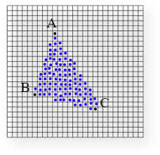
To create the method I followed this tutorial: https://www.scratchapixel.com/lessons/3d-basic-rendering/rasterization-practical-implementation/rasterization-stage
Author
Gotanod said:
Anyway, try to multiply the vertex_clip_position with this matrix, where sW = frame width in pixels, sH= frame Height in pixels.
Where is the part where I divide the x, y by the w? That's what I know I should do in order to project the 3D to 2D
@bogdan7 This is a good page to know all the details
http://www.songho.ca/opengl/gl_transform.html
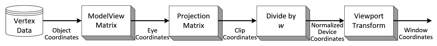
Usually we use the PVM matrix (projection/view/model) to draw correctly the objects without taking care of the w or the viewport (we provide that with an initial call to se the viewport).
We just multiply in the vertex shader → PVM * vertex_position … without taking care of the w, the view port, … It works ?
But if I remember well, the GPU does several extra actions for you. That you will need to do manually.
- Divide by w
- Clip the shapes/geometry.
- Transform to view coordinates.
- Depth buffer
- …
Divide by w or transforming to view coordinates can be achieved easily multiplying with matrices.
In my opinion, the hardest one is the “Clip shapes/geometry”. NDC coordinates are between [-1,1] for each axis if the object is viewable by the camera…
But what happens if the result is greater than 1 or lower than -1, it must be removed from the draw operation. Easy.
But what happens if the object is partially viewable by the camera/eye. It must be clipped or draw only partially.
In the below picture from “Fligths of Fantasy” you can see how an initial geometry of a triangle is transformed in a four vertices polygon. You need to draw the polygon only, the left part is outside your window. Of course, you can take care of that in your method “Screen.Interpolation” taking care of the pixels outside the limits. But it will be less efficient.
The book "Fligths of Fantasy" 1993 shows all the process. I think it is the same that you are doing.
https://www.amazon.com/Flights-Fantasy-Programming-Christopher-Paperback/dp/B011W9Z4US

This topic is closed to new replies.
Advertisement
Popular Topics


Advertisement
