Not many can claim 25 years on the Internet! Join us in celebrating this milestone. Learn more about our history, and thank you for being a part of our community!
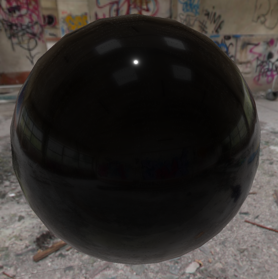
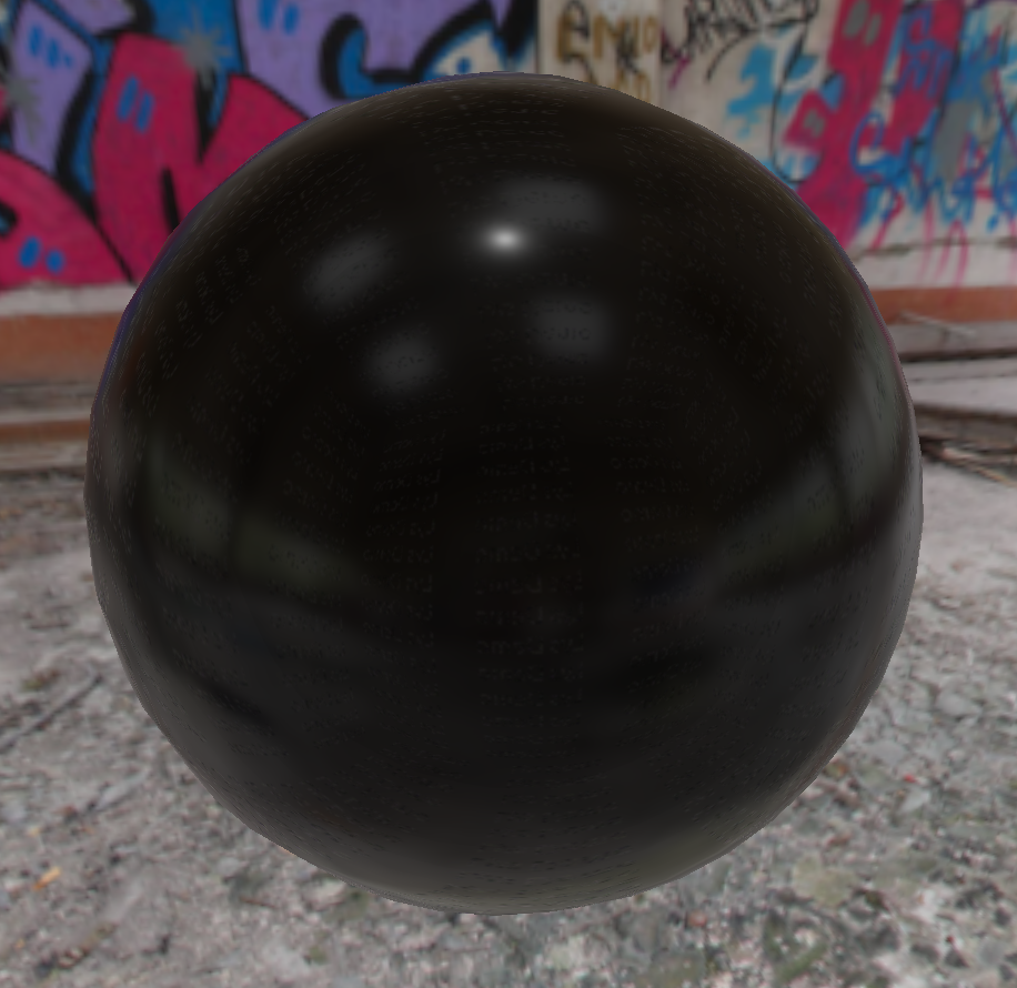
I’m confused by the fact that my specular highlight doesn’t quite line up with the light in my IBL cubemap. Before I go into any code, has anyone noticed this before?
I’ve set my light vector to match the vector that goes from 0,0,0 to what would be the simulated light in the cubemap but when I move the camera around my sphere, the position of the specular highlight never really matches the position of the image light. It’s close, but I’ve noticed in the unreal editor that the specular highlight on their sphere matches where the sun would be on the cubemap.
I’m thinking it’s to do with how the cubemap sampler works and maybe that it works from the centre of the cubemap whereas the pixel(s) in question aren’t at the centre of the cubemap.
A picture would help. That being said, if some sort of box projection “cubemap position” is taken into account then yes, sun highlights should end up looking “wrong”.
For practical purposes the sun in almost any setting should be “inifinitely” far away, and so while rotation will change lighting (either rotation of the sun or of objects) an object's position or movement along xyz shouldn't affect how its lit from the sun (other than being in a shadow). Thus if it's baked into a cubemap that isn't “infinitely far away” it'll look wrong.
That's just a guess though, as stated, a picture, or even better a video, would help a lot.
I’ll try and post one up tomorrow. I don’t think this is an issue particularly as it’ll probably never be noticed on anything other than a very smooth plastic-type surface, I just wanted to understand really why the specular position doesn’t move in tandem with the specular reflection from the cubemap. The specular reflections ‘skew’ around the sphere as you'd expect and so does the specular highlight, they just never quite align properly.
Thinking about this further, when you get your reflected pixel colour from the cubemap, your pixel world position is effectively moved to the centre of the cubemap and the reflection vector is used from there to sample the map. This isn’t really physically correct, what should happen is that you’d project a reflection vector from the world position of the pixel into the cubemap. This might be why you can’t match the specular highlight with what’s in the IBL cubemap. I can’t quite work the practicalities out in my head (my maths is limited) but I’m sure this is something to do with it.
That's essentially what Frantic PonE was getting at with the “inifinitely far away” bit: if you just map your reflection vector directly to the cubemap you're not getting any parallax, which means it's only correct if what's in the cubemap is infinitely far away from the reflection surface.
The other thing to keep in mind is that Cook-Torrance specular BRDF's don't necessarily have their peak exactly aligned with the reflection vector (in fact the famous Torrance-Sparrow paper that Cook and Torrance built upon was called “Theory for Off-Specular Reflection From Roughened Surfaces”). In general it should still be pretty close, but things will get weirder for glancing angles.
Thanks guys, I've got a bit further with this now. I was messing around with different BRDF approaches last night and I thought I'd try the ubiquitous combination of Schlick Fresnel, D_GGX and Smith GGX Correlated (I may have those incorrect so apologies to any authors…). There are a lot of images here (who doesn't love an image?!) and two questions, I hope I'm not overstepping the mark with your assistance but I'm very confused (especially by the second question).
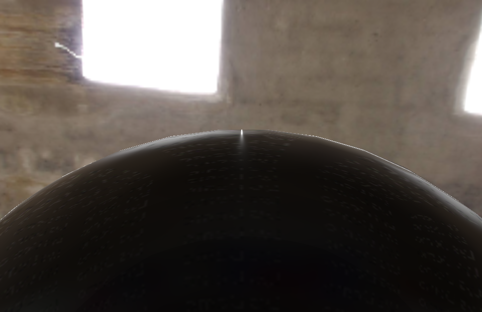
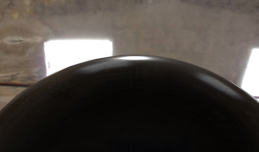
I'll start off by saying that there's one thing that really bugs me about specular highlights using this method, and it's this:
Specular highlight at grazing angles do not conform to the surface they're on - this looks weird to me.
And, at a slight tighter grazing angle:
Specular highlight looks really wrong now
And then….
Can't even begin to understand what's happening here.
These, to me look physically incorrect. You even get the same specular shape in UE4:
Unreal Editor 4
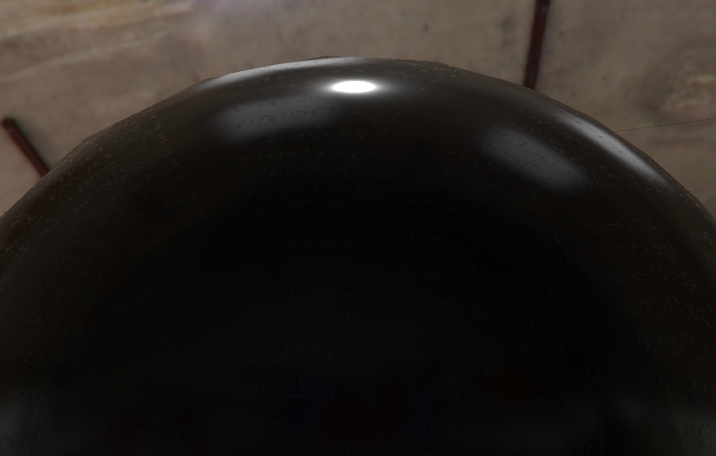
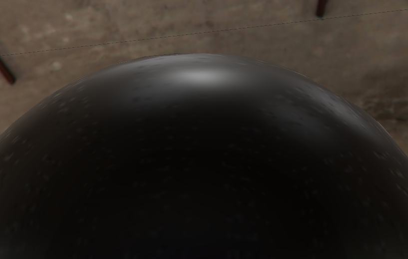
This has always bugged me and it doesn't reflect what's in the real world so I went about playing around with my own BRDF which never really got far because my maths is terrible, but I managed to get my highlights looking like this using the Schlick, Smith, Cook-Torrance BRDF mentioned above:
Grazing angle specular highlight looks more like it wraps around the sphere as it would in the real world
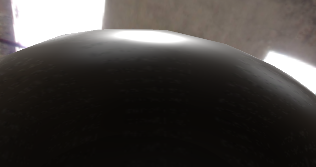
Here's a tighter grazing angle:
Highlight is stretched around the sphere - perfect (in my opinion)
It also looks pretty nice with some roughness:
Ignore the weird artefacts to the left and right, that's advertising on my environment map.
So I'm really happy with this and it looks more realistic but I have a couple of issues…
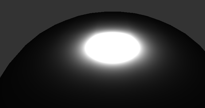
Firstly, at more severe grazing angles, the brightness of the highlight seems to increase exponentially. Here's an example:
This image is using the same roughness value (0.5) as the image above, but as the grazing angle is flatter, so to speak, the brightness of the highlight begins to look unrealistic.
I think this is happening in the Smith GGX Correlated function:
I haven't changed anything there, it's pretty standard I believe. If I render with just the Distribution function:
float _D_GGX(float NoH, float a) {
float a2 = a * a;
float f = (NoH * a2 - NoH) * NoH + 1.0;
return a2 / (PI * f * f);
}
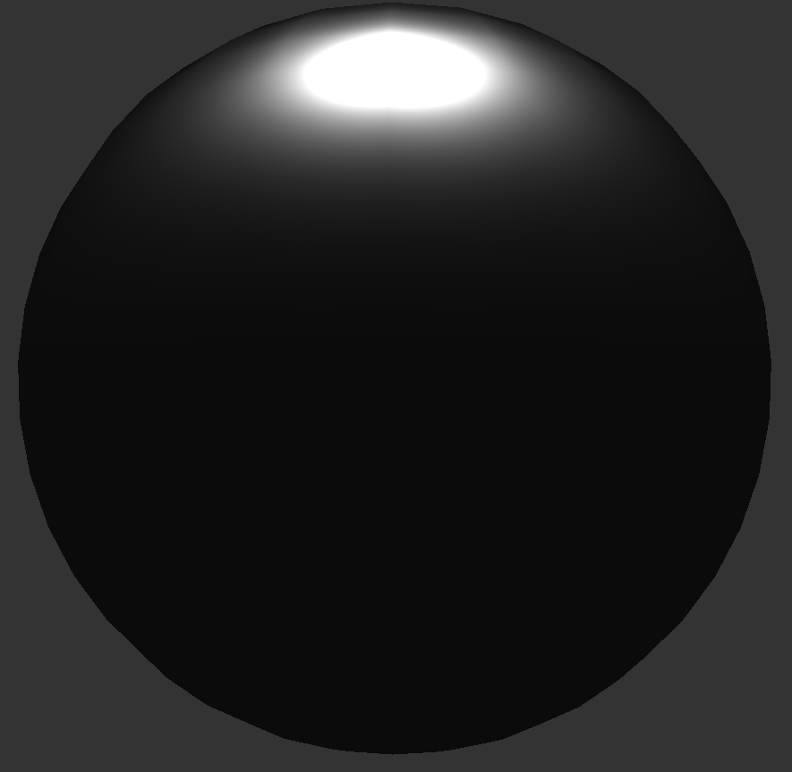
Which is also standard and not changed, I get the following large highlight (as it's not diluted by the SmithGGX function):
Not quite grazing angleFull grazing angle
If I multiply in the rest of the BRDF, I get the following:
Full grazing angle with D x G x F
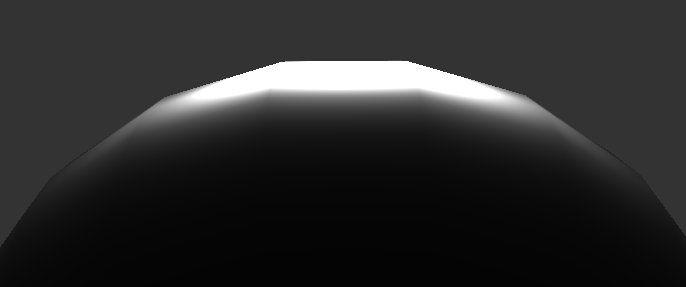
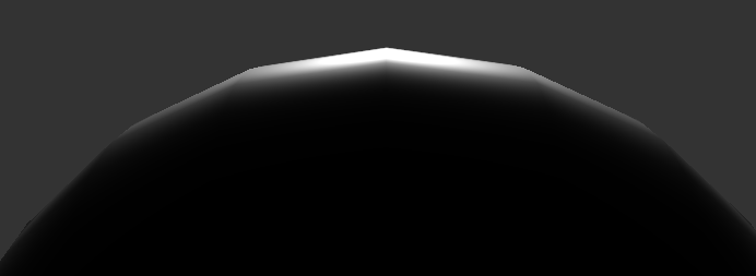
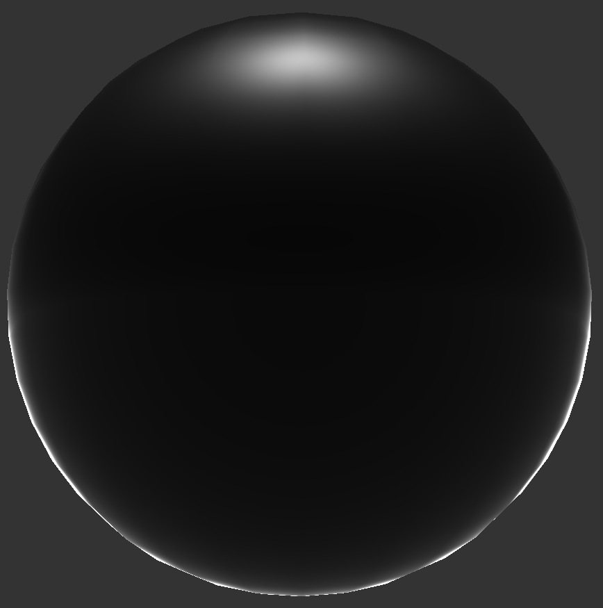
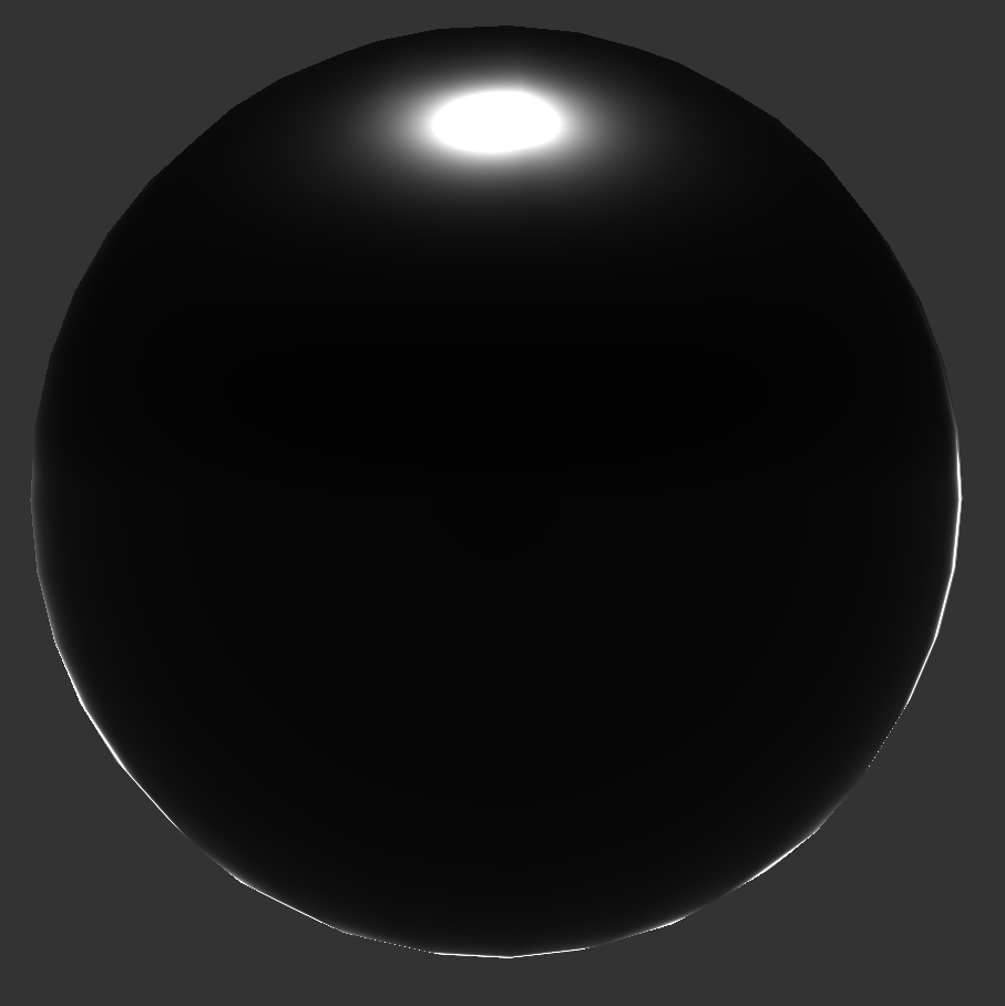
I don't think this is quite right so my first question - is there anything mathematically that can be done to the SmithGGXCorrelation function to stop it from brightening at grazing angles? Here are two images of the SmithGGXCorrelation function at slight different grazing angles - you can see that the flatter the angle, the light it gets which is causing the highlight to get very bright when all parts of the BRDF are applied:
SmithGGXCorrelation at steep(ish) grazing angleSame image but at flatter grazing angle. Notice the area that will darken (distribute) the specular highlight is lighter and so makes the highlight brighter.
Here's the second part of my question and it's a strange one. Ignoring the highlight issue, I also get a bright ring around my sphere at certain angles and it doesn't make any sense.
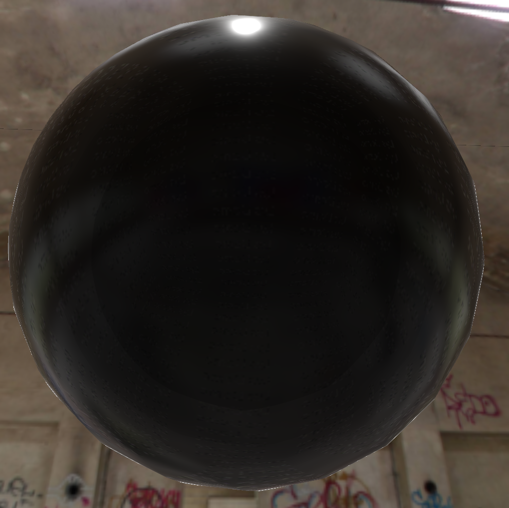
Here's an image of the sphere from above (the light is directly above too, but it has a high roughness value):
Sphere from above, Fresnel looks okay
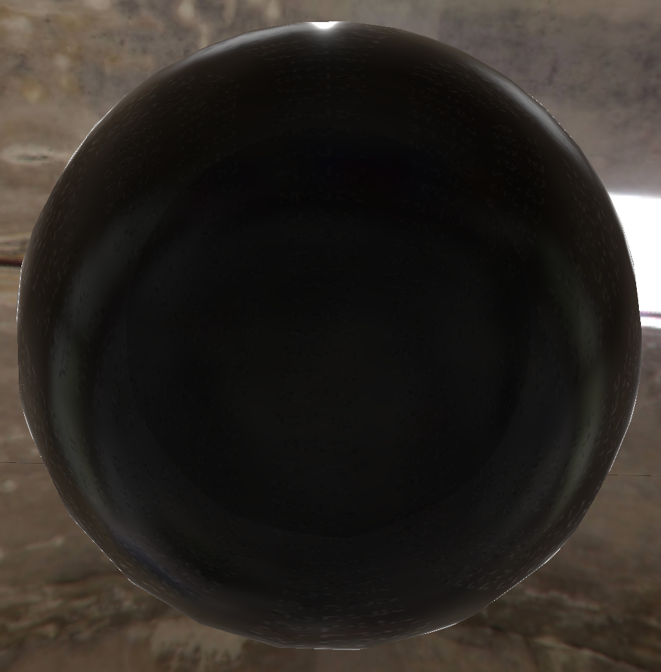
And one with no roughness:
Fresnel looks okay
So now if I ramp the roughness up and take a snapshot from a different angle, I get an ugly white blotchy edge:
This is in my sample window, still using the same environment map and material. See the ugly white edge on the bottom.
Strangely, if I only render two of the three components of the BRDF, the D and the G (ignoring Frensel), I still get the edge (the highlight is bigger as Fresnel isn't applied):
D_GGX and SmithGGXCorrelated combined. This is a simple multiplication of D and G and I just return the value.
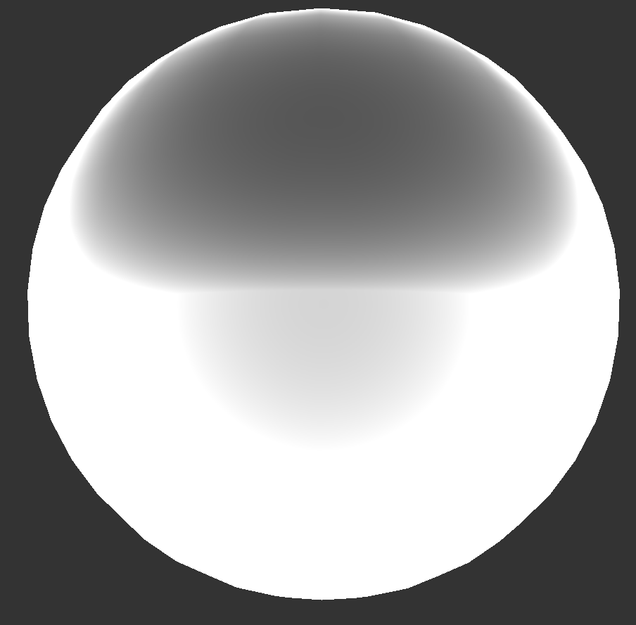
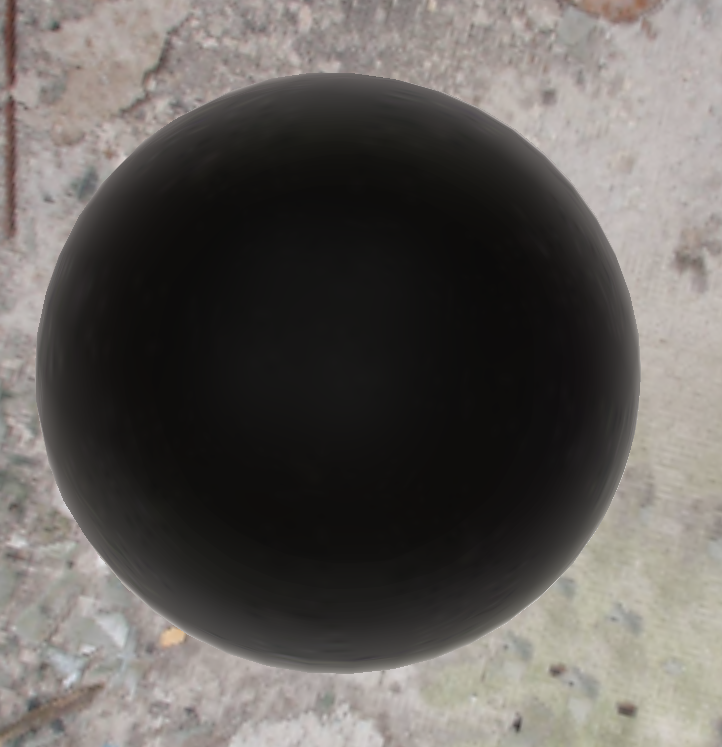
Now it gets really weird because if I render the D and G separately, one is black and one is white:
D_GGX only - the edge is not absolutely black, but it's pretty close.SmithGGXCorrelated only. Around the bottom edge, it's white all over.
So my second question is, how on earth can these two images combined, give me the one with the ugly edge? This is the code:
I can't see any way that the edge can appear with 0.0 * 1.0 in those areas. The actual values are around 2-6 (out of 255) but nowhere near high enough to allow the white through…
Edit: I've fixed the second part to this post. I realised that the results from the D and V functions were returning far greater than 1.0 for some pixels (obviously, doh!) and so my 2-6 values around the edge were being multiplied by far greater than 1.0 to give white. I fixed this by saturating the GGXSmithCorrelated function: